Guide to TSOP IR receiver

TSOP IR Receiver 

http://dmohankumar.files.wordpress.com/2011/12/tsop-1738.jpgTsop is an IR receiver which will help you to interface your TV remote with arduino.

The TSOP outputs a constant HIGH signal when idle and as it receives data, it tends to invert the data. i.e when an IR LED is transmitting data onto the TSOP, every time the IR led goes high, the TSOP will go LOW and vice versa. Remote control signals are often bytes of data that is encoded and transmitted by pulsing(switching ON & OFF the IR LED at a specific frequency) Most TV remote controls work at 32-40 Khz frequency and most receivers can receive this range. 

The SIRC protocol uses a pulse width encoding of the bits. The pulse representing a logical "1" is a 1.2ms long burst of the 40kHz carrier, while the burst width for a logical "0" is 0.6ms long. All bursts are separated by a 0.6ms long space interval.


Modulation


If you look at the image, you can see the the 1.2ms high of the Logical '1' has further black lines with spaces in between. These correspond to the ON/OFF cycles. The space between these is what is called the frequency. The frequency of occurrence of a ON/OFF cycle is what it means.

The black bars in the below image correspond to high signals (called marks) and the white spaces in between correspond to low signals (called spaces). The duration of the 'marks' varies according to the bit being transmitted. It is 2.4ms for the start bit, 1.2ms for HIGH bit and 0.6ms for LOW bit. The duration of the 'spaces' is a constant 0.6ms. Every mark is followed by a space. Any data can be converted to binary format and transmitted in this manner. In fact this is the basic form of all types of serial communication.


SIRC Modulation


Protocol

SIRC Pulse Train

 LSB=least significant bit

MSB= Most significant bit


The picture above shows a typical pulse train of the SIRC protocol. With this protocol the LSB is transmitted first. The start burst is always 2.4ms wide, followed by a standard space of 0.6ms. Apart from signalling the start of a SIRC message this start burst is also used to adjust the gain of the IR receiver. Then the 7-bit Command is transmitted, followed by the 5-bit Device address. In this case Address 1 and Command 19 is transmitted.Commands are repeated every 45ms(measured from start to start) for as long as the key on the remote control is held down. 

 Please click here for more info --->http://www.sbprojects.com/knowledge/ir/sirc.php


Here's a basic outline of how the data is sent. Every time you press a button on a Sony remote control, it sends out a 13Bit data. The first bit is a start bit indicating there are 12 bits of data following it. The next 7 bits are the command bit which will vary depending upon the keys being pressed. The last 5 bits are the address bits which will the same for all buttons but vary for remote controls of different devices. 

Calculating the pulse.

The pulse of the transmiton can be calculated using the pulse in function --->  http://arduino.cc/en/Reference/pulseIn 


Here's the code, You can plug in the remote function into any of your programs, just remember to declare pin 15 as INPUT.

  void setup()  
 {  
  pinMode(15,INPUT); // TSOP is connected on the 15ht pin  
  Serial.begin(9600);  
 }  
 void loop()  
 {  
  int remote_val = remote();  
  if(remote_val>0)  
  {  
   Serial.println(remote_val);  
   delay(150); // A remote press will normally generate 3 signal trains. This is to avoid reading duplicates  
  }  
 }  
 int remote()  
 {  
  int value = 0;  
  int time = pulseIn(15,LOW);  
  if(time>2000) // Checking if the Start Bit has been received. Start Bit Duration is 2.4ms  
  {  
   for(int counter1=0;counter1<12;counter1++) // A loop to receive the next 12 bits  
   {  
    if(pulseIn(15,LOW)>1000) // checking the duration of each pulse, if it is a '1' then we use it in our binary to decimal conversion, '0's can be ignored.  
    {  
     value = value + (1<< counter1);// binary to decimail conversion. 1<< i is nothing but 2 raised to the power of i  
    }  
   }  
  }  
  return value;  
 }  


To remove all these complications, we can also use Ir remote library which can be downloaded at http://arcfn.com/files/IRremote.zip
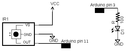
IR wiring
Hardware connection Tsop (left)


The examples/IRrecvDemo sketch provides a simple example of how to receive codes: 

#include <IRremote.h>

int RECV_PIN = 11;
IRrecv irrecv(RECV_PIN);
decode_results results;

void setup()
{
  Serial.begin(9600);
  irrecv.enableIRIn(); // Start the receiver
}

void loop() {
  if (irrecv.decode(&results)) {
    Serial.println(results.value, HEX);
    irrecv.resume(); // Receive the next value
  }
}


Ethernet shield Guide for arduino

Arduino Ethernet Shield

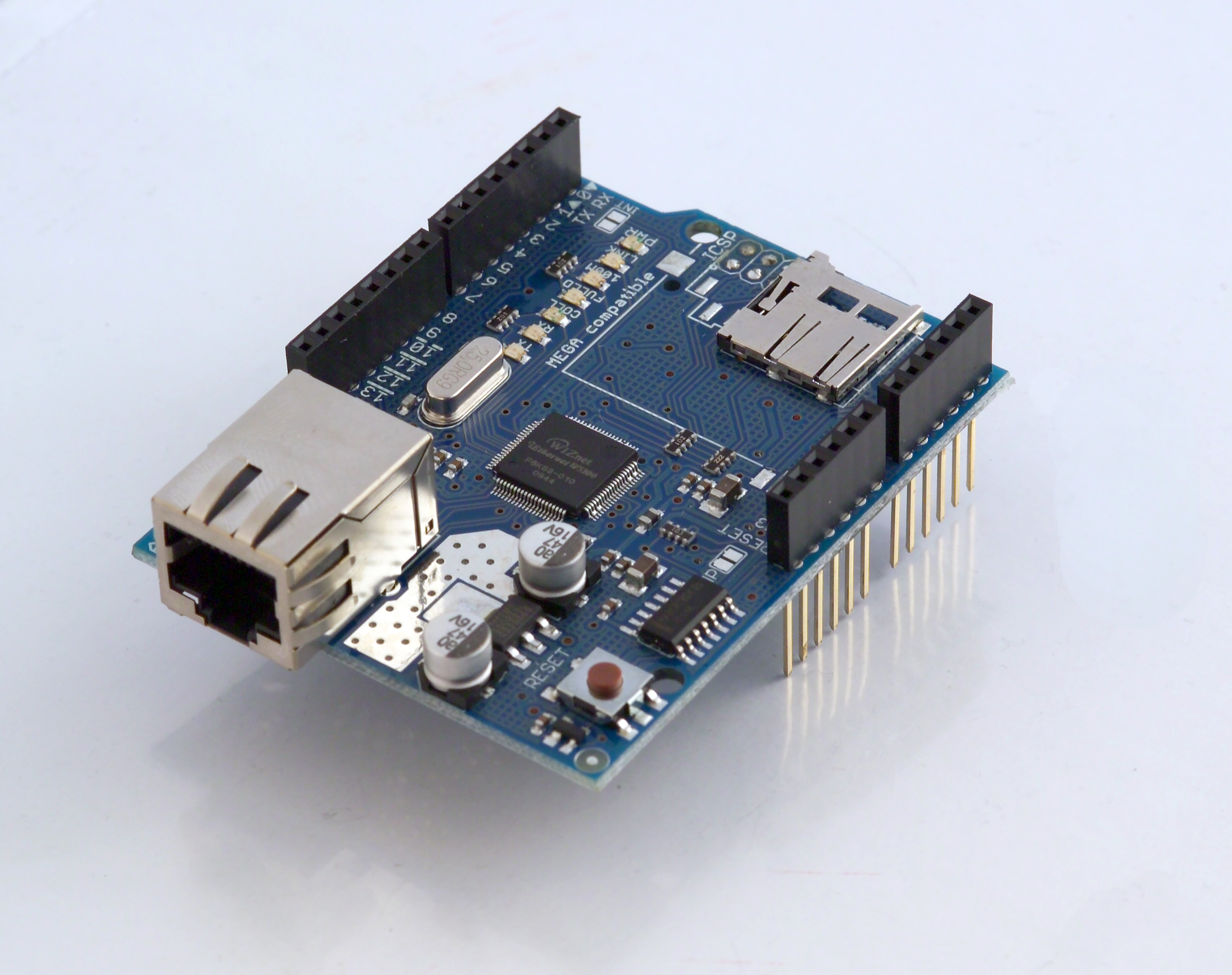
The Arduino Ethernet shield allows an Arduino board to connect to the internet using the Ethernet library and to read and write an SD card using the SD library.

Connecting the Shield

To use the shield, mount it on top of an Arduino board (e.g. the Uno). To upload sketches to the board, connect it to your computer with a USB cable as you normally would. Once the sketch has been uploaded, you can disconnect the board from your computer and power it with an external power supply.
Connect the shield to your computer or a network hub or router using a standard ethernet cable (CAT5 or CAT6 with RJ45 connectors). Connecting to a computer may require the use of a cross-over cable (although many computers, including all recent Macs can do the cross-over internally).

Network Settings

The shield must be assigned a MAC address and a fixed IP address using the Ethernet.begin() function. A MAC address is a globally unique identifier for a particular device. Current Ethernet shields come with a sticker indicating the MAC address you should use with them. For older shields without a dedicated MAC address, inventing a random one should work, but don't use the same one for multiple boards. Valid IP addresses depend on the configuration of your network. It is possible to use DHCP to dynamically assign an IP to the shield. Optionally, you can also specify a network gateway and subnet.

SD Card

The latest revision of the Ethernet Shield includes a micro-SD card slot, which can be interfaced with using the SD library


Connecting the Ethernet shield


 The Arduino Ethernet Shield allows you to easily connect your Arduino to the internet. This shield enables your Arduino to send and receive data from anywhere in the world with an internet connection. You can use it to do fun stuff like control robots remotely from a website, or ring a bell every time you get a new twitter message. This shield opens up endless amounts of possibility by allowing you to connect your project to the internet in no-time flat.


setting it up is as simple as plugging the header pins from the shield into your Arduino.


Setup


There is also an on-board micro SD slot which enables you to store a heck-of-a-lot of data, and serve up entire websites using just your Arduino. This requires the use of an external SD library, which does not come bundled with the software.


plug the Arduino into your computer's USB port, and the Ethernet shield into your router (or direct internet connection).


Next, open the Arduino development environment. I highly recommend upgrading to Arduino 1.0 or later (if you have not done so already). This version of the software has built in DHCP support, and does not require manually configuring an IP address.


To figure out what IP address has been assigned to your board, open the DhcpAddressPrinter sketch. This can be found at:


File --> Examples --> Ethernet --> DhcpAddressPrinter


Once open, you may need to change the Mac address. On newer versions of the Ethernet shield, you should see this address on a sticker attached to the board. If you are missing a sticker, simply making up a unique mac address should work. If you are using multiple shields, make sure each has a unique mac address.


Once the mac address is properly configured, upload the sketch to your Arduino, and open the serial monitor. It should print out the IP address in use.


The following code lights up an LED depending on the URL that is sent to the Arduino:


/*
  Web Server Demo
  thrown together by Randy Sarafan

 Allows you to turn on and off an LED by entering different urls.

 To turn it on:
 http://your-IP-address/$1

 To turn it off:
 http://your-IP-address/$2

 Circuit:
 * Ethernet shield attached to pins 10, 11, 12, 13
 * Connect an LED to pin D2 and put it in series with a 220 ohm resistor to ground

 Based almost entirely upon Web Server by Tom Igoe and David Mellis

 Edit history:
 created 18 Dec 2009
 by David A. Mellis
 modified 4 Sep 2010
 by Tom Igoe

 */

#include <SPI.h>
#include <Ethernet.h>

boolean incoming = 0;

// Enter a MAC address and IP address for your controller below.
// The IP address will be dependent on your local network:
byte mac[] = { 0x00, 0xAA, 0xBB, 0xCC, 0xDA, 0x02 };
IPAddress ip(191,11,1,1); //<<< ENTER YOUR IP ADDRESS HERE!!!

// Initialize the Ethernet server library
// with the IP address and port you want to use
// (port 80 is default for HTTP):
EthernetServer server(80);

void setup()
{
  pinMode(2, OUTPUT);

  // start the Ethernet connection and the server:
  Ethernet.begin(mac, ip);
  server.begin();
  Serial.begin(9600);
}

void loop()
{
  // listen for incoming clients
  EthernetClient client = server.available();
  if (client) {
    // an http request ends with a blank line
    boolean currentLineIsBlank = true;
    while (client.connected()) {
      if (client.available()) {
        char c = client.read();
        // if you've gotten to the end of the line (received a newline
        // character) and the line is blank, the http request has ended,
        // so you can send a reply
       
        //reads URL string from $ to first blank space
        if(incoming && c == ' '){
          incoming = 0;
        }
        if(c == '$'){
          incoming = 1;
        }
       
        //Checks for the URL string $1 or $2
        if(incoming == 1){
          Serial.println(c);
         
          if(c == '1'){
            Serial.println("ON");
            digitalWrite(2, HIGH);
          }
          if(c == '2'){
            Serial.println("OFF");
            digitalWrite(2, LOW);
          }
       
        }

        if (c == '\n') {
          // you're starting a new line
          currentLineIsBlank = true;
        }
        else if (c != '\r') {
          // you've gotten a character on the current line
          currentLineIsBlank = false;
        }
      }
    }
    // give the web browser time to receive the data
    delay(1);
    // close the connection:
    client.stop();
  }
}


To make this work connect the positive lead an LED to pin D2, and the negative lead in series with a 220 ohm resistor to ground.


To turn on the LED enter this into your browser:
http://[YOUR IP ADDRESS HERE]/$1


To turn off the LED enter this into your browser:
http://[YOUR IP ADDRESS HERE]/$2


Note: You should obviously replace [YOUR IP ADDRESS HERE] with your IP address.


click to know your ip --> whatismyip


 Sources: instructables, google, arduino.cc